- Measure Level or Open Channel Flow
- User-Friendly Calibration System
- Isolated 4-20mA (1000 ohm)
- False Echo Rejection
- 2 Programmable Control Relays
- Electrical Surge Protection
- Intrinsically Safe Sensor Option
- Plug and Play Relay and Data Logger Options
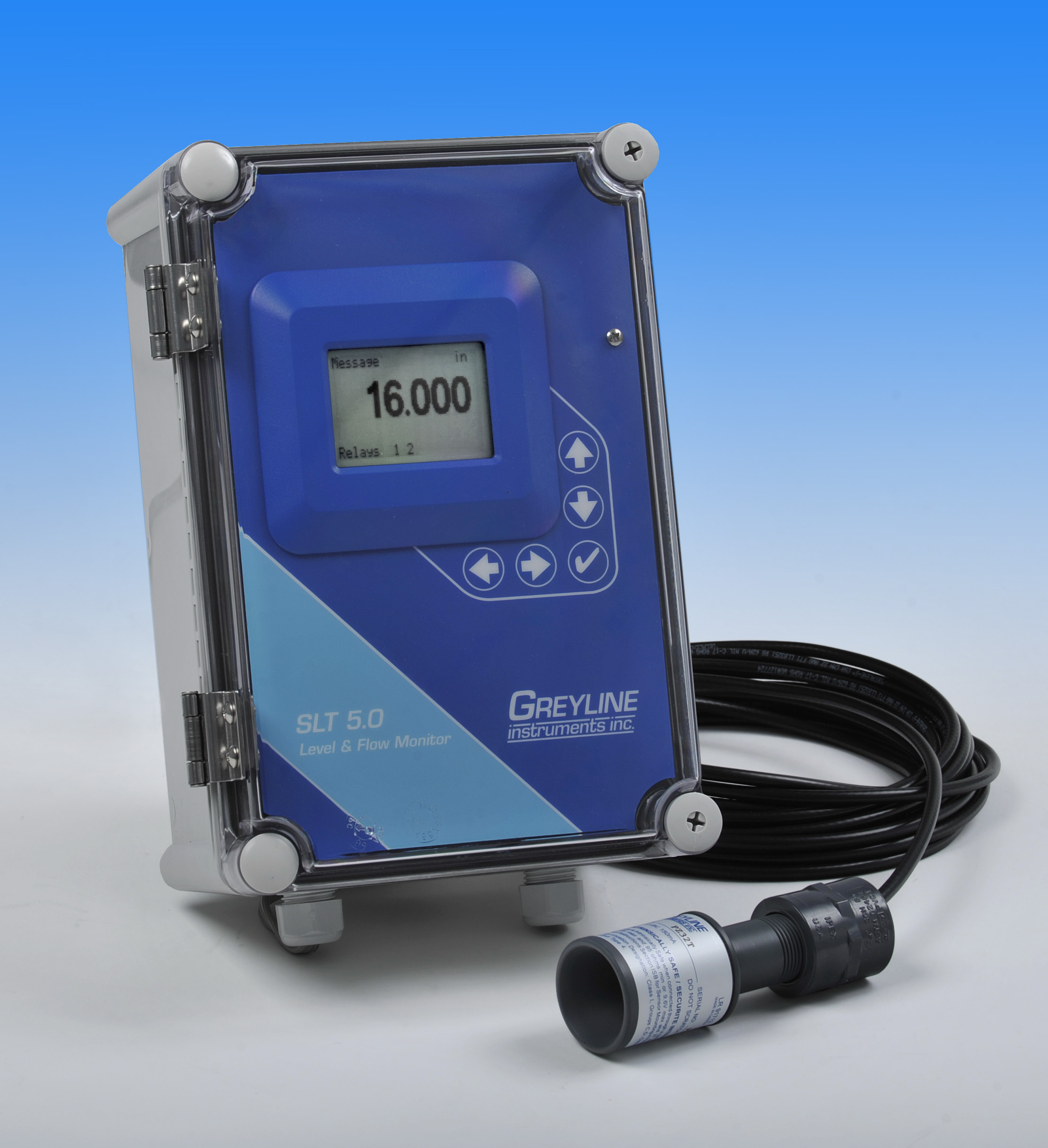
SLT 5.0 Ultrasonic Level & Flow Monitor
SLT 5.0 Level & Flow Monitor
Use this versatile instrument to continuously measure, display, transmit and control liquid level in storage tanks and pumping stations, or to monitor and totalize Open Channel Flow through any flume or weir. Mount the non-contacting ultrasonic sensor above the liquid being measured and install the watertight electronics enclosure nearby. Features a user-friendly keypad calibration system, backlit LCD display, an isolated 4-20mA output and 2 programmable control relays.
Calibration is easy with the built-in 5 button keypad. The SLT 5.0 offers simple menu selection of measurement units (gallons, liters etc.), calculates volume in horizontal round tanks, or flow rate (and total) through any flume or weir.
For hazardous locations, the ultrasonic sensor is rated Intrinsically Safe with an optional safety barrier. The standard PVC and Teflon Sensor is rated for measurement ranges up to 32 ft/10 m, or select optional sensors for flange-mount or applications requiring longer measurement range. Options include 4 additional control relays (6 total) and a built-in 2-million point Data Logger with USB output to Flash memory sticks.
Contact Greyline Instruments for specific recommendations in your application.
LEVEL & FLOW MONITOR SPECIFICATIONS
SCOPE: This specification covers a non-contacting ultrasonic Level/Flow Monitor as manufactured by Greyline Instruments, Massena New York / Long Sault, Ontario. This instrument shall provide for indicating, transmitting and control of the material level in a vessel or proximity of a target to the instrument sensor, and indicating, transmitting, and totalizing of the flow rate through a flume, weir, or other primary measuring device.
A. GENERAL
- Level/Flow Monitor to consist of an non-contacting ultrasonic sensor, connecting cable, and a remote enclosure with indicating, transmitting and controlling electronics.
- Measurement accuracy shall be ±0.25% of Range or 2 mm (0.08"), whichever is greater, and shall be automatically temperature compensated.
- Sensor cable length shall be as required by installation, not to exceed 500' (152 m).
- System shall have no moving parts and shall not contact the material being measured.
- Shall include PC software program disk to determine open channel flow calibration values for non-standard flumes and weirs.
B. SENSING ELEMENT
- Sensor shall be constructed of PVC and Teflon.
- The sensor shall have a minimum deadband or blanking of 12" (305 mm) and a maximum range of 32 ft. (10 m), and have an operating frequency of 42 kHz with an ultrasonic beam angle of 8 Degrees.
- Sensor shall withstand accidental submersion to 20 psi.
- Sensor operating temperature shall be from -40°F to 150°F (-40°C to 65°C).
- Sensor shall include integral temperature sensor. Temperature sensors requiring separate mounting and wire runs shall not be accepted.
C. SENSOR CONNECTING CABLE
- Provide RG62AU coaxial cable 25' (7.6m) continuous length, with waterproof, potted bond to the Sensor head.
- Extended sensor cable shall be RG62AU coaxial to a maximum of 500' (152m). Cable shall be spliced with screw terminal connections in manufacturer's recommended steel NEMA4 Junction Box.
- Level and temperature signals shall be conducted on one single coaxial cable. Separate or multiple-conductor cables shall not be accepted.
- Sensor cable shall be installed in grounded metal conduit.
D. TRANSMITTER
- The transmitter shall provide for field-calibration via built-in 5-key calibration system with menu selection of parameters. Systems requiring calibration by Parameter codes, BCD switches or external calibrators shall not be accepted.
- Calibration data shall be password protected and permanently stored through power interruptions for a minimum of 12 months.
- Field calibration shall allow selection and automatic conversion of measurement units, measurement span and control relays.
- The transmitter shall provide for field calibration in user-selected Range, Level or Open Channel Flow modes. Flow mode shall allow calibration to common primary metering devices, plus allow entry of calibration formula for non-standard flumes, weirs or open channels.
- Transmitter shall permit field programmable damping to smooth output with turbulent level.
- Transmitter operating temperature shall be from -5° to 140°F (-20° to 60°C). Transmitter shall contain a thermostat-controlled enclosure heater for condensation protection below 30°F (-1°C).
- Transmitter shall have an isolated 4-20mA output rated for 1000 ohm maximum load with menu-selectable 0-5VDC alternative.
- Provide two relay contacts rated 5 amp SPDT programmable for single set point alarms, dual set point pump control, pump alternation, temperature alarm, flow totalizer pulse and/or echo loss alarm.
- Provide a white, backlit matrix LCD display indicating flow rate, level, velocity, totalizer and relay states in user-selected engineering units.
- Transmitter display indicating level or flow rate, units of calibration, totalizer and relay states shall be visible without opening cover.
- Transmitter shall be housed in a wall-mount, watertight NEMA4X (IP66) enclosure with hinged, clear cover. Mounting hardware shall be included.
- Transmitter electronics shall be surge protected on AC power input, sensor and 4-20mA outputs.
- Transmitter power input shall be 100-240VAC 50-60Hz with power consumption of 3.5 Watts or less.
- The transmitter shall permit plug-in field installation and auto-detection of optional accessories including data logger and additional control relays.
E. OPTIONAL FEATURES FOR INSERTION AS REQUIRED
- Have 4 additional (6 total) control relays, rated 5 amp SPDT and programmable for single set point alarms, dual set point pump control, pump alternation, temperature alarm, flow totalizer pulse and/or echo loss alarm.
- Sensor, connecting cable and junction boxes shall be rated intrinsically safe to Class I,II,III, Div. I,II, Groups C,D,E,F,G.
- Have a thermostat controlled enclosure heater for Transmitter operation at temperatures below freezing.
- Have an all-Teflon sensor Model PZ32TE rated intrinsically safe when connected through an approved safety barrier, and rated for operation from -40°F to 170°F (-40°C to 76°C).
- Have a PVC and Teflon sensor Model PZ56 rated for measurement range on liquids up to 50 ft. (15.6 m).
- Have a Teflon-faced flange mount sensor model PZ34TxF rated for 32 ft (10 m) measurement range. Specify flange size of 4” or 6”.
- Have manufacturer's recommended enclosure sunscreen to permit Transmitter mounting in direct sunlight.
- Have manufacturer's recommended Sensor sunscreen to permit temperature-compensated Sensor mounting in direct sunlight.
- Have manufacturer's recommended Panel Mount Flange assembly for enclosure installation.
- Have a built-in 2 million point Data Logger with USB output to flash drive or mass storage device. Include Windows software.
- Have power input of 9-32VDC and power consumption of less than 3.5 Watts.
F. MANUFACTURER