
- For Open Channels and Pipes No Flume or Weir Required
- Ultrasonic - Measures Velocity + Level to Calculate Flow
- Works in partially filled and surcharged pipes
- 3 Isolated 4-20mA Outputs(Flow, Level and Velocity)
- Isolated 4-20mA/0-5V Output
- Totalizer and 2 Control Relays
- Optional Intrinsically Safe Sensor
- Optional built-in 2-million point Data Logger
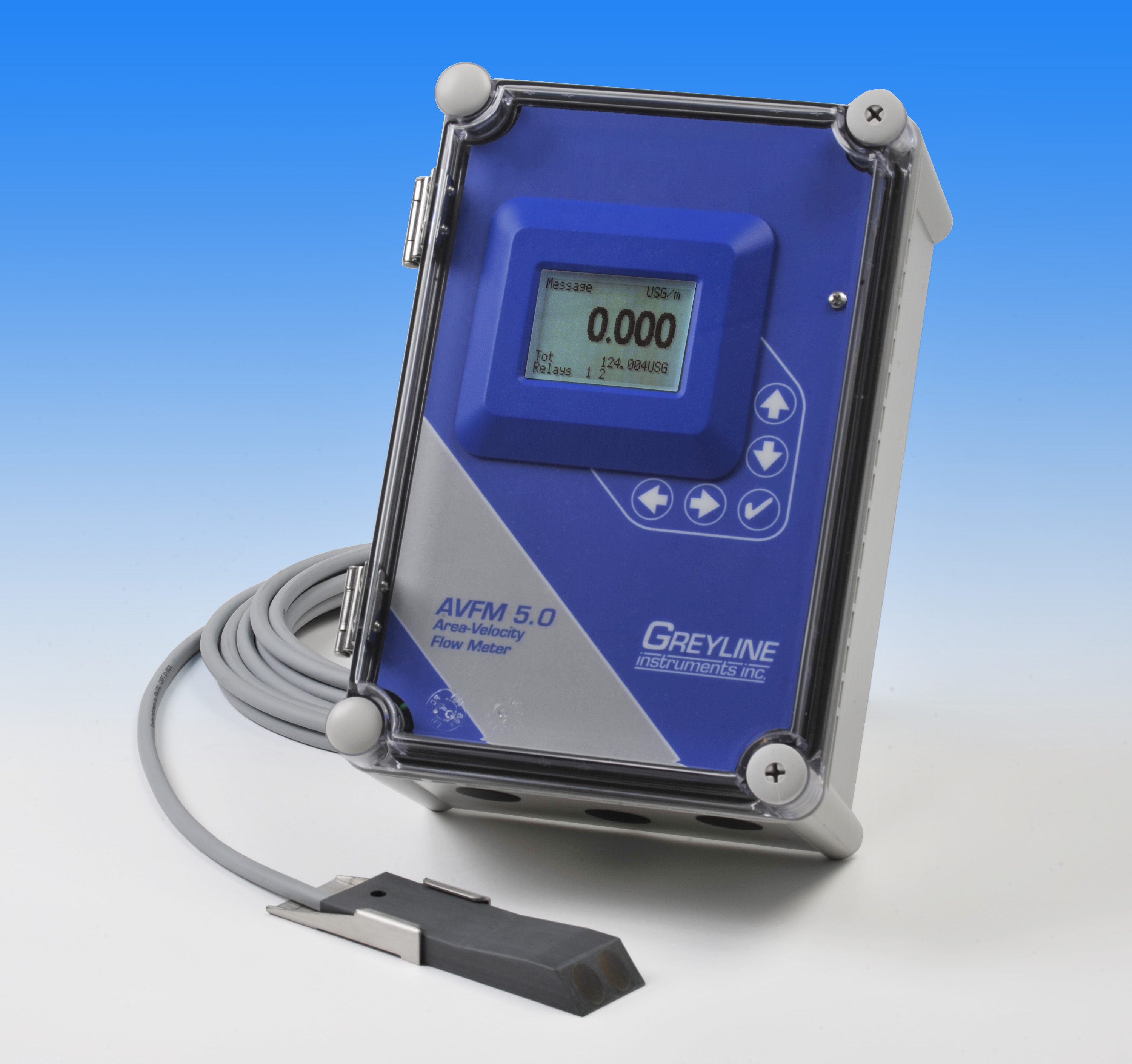
AVFM 5.0 Area-Velocity Flow Monitor
Monitor flow through open channels, partially full sewer pipes and surcharged pipes without a flume or weir. Ideal for stormwater, combined effluent, raw sewage, irrigation water and streams. Calibration is simple: enter the pipe diameter or channel shape and the AVFM 5.0 computes the flow volume and displays the flow rate. Measure forward and reverse flow and calibrate to channels of any shape.
How It Works 
The AVFM 5.0 uses a submerged ultrasonic sensor to measure both Velocity and Level in the channel. The sensor is completely sealed with no orifices or ports. It mounts inside a pipe or at the bottom of a channel.
Contact Greyline Instruments for specific recommendations in your application.
AREA-VELOCITY FLOW MONITOR SPECIFICATIONS
SCOPE: This specification covers an ultrasonic, area-velocity flow monitor as manufactured by Greyline Instruments, Massena, New York / Long Sault, Ontario. The instrument shall provide for indicating, transmitting, totalizing of the flow rate through partially filled or surcharged round pipes and rectangular, trapezoidal, egg or irregular shaped open channels.
A. GENERAL
- Flow Monitor to consist of a submersible ultrasonic sensor, connecting cable, and remote enclosure with indicating, transmitting and controlling electronics. System shall have no moving parts.
- Level measurement accuracy shall be ±0.25% of Range. Velocity measurement accuracy shall be ±2% of reading.
B. SENSING ELEMENT
- Ultrasonic sensor shall be rated IP68 for continuous submersion in liquids.
- Using the Doppler principle, the sensor shall measure fluid velocities from 0.1 to 20 ft/sec (0.03 to 6.2 m/sec) and reverse flow to -5 ft/sec (-1.5 m/sec).
- Using ultrasonic echo-ranging principle, the submerged sensor shall measure liquid level from 1" to 15 ft. (25.4 mm to 4.57 m).
- Level sensing circuitry shall include a temperature sensor for automatic temperature compensation.
- Sensor shall be constructed of PVC and epoxy resin.
- Sensor operating temperature shall be 5°F to 150°F (-15°C to 65°C).
- Shall include manufacturer's recommended stainless steel sensor mounting bracket.
C. SENSOR CONNECTING CABLE
- Provide minimum length 25 ft (7.6 m) tri-coaxial cable with potted bond to the Sensor head. Sensor cable shall be waterproof and electrically shielded. Exposed material shall be polyurethane only.
- Extended sensor cable shall be shielded tri-coaxial to a maximum length of 500 ft (152m). Cable shall be spliced with screw terminal connections in manufacturer’s recommended steel NEMA4 Junction Box.
D. TRANSMITTER
- The transmitter shall provide for field calibration to round pipes and open channels of any shape.
- Calibration shall be via built-in 5-key calibration system with menu selection of parameters. Systems requiring calibration by Parameter codes, BCD switches or external calibrators shall not be accepted.
- Calibration data shall be password protected and permanently stored through power interruptions for a minimum of 12 months.
- Field calibration shall allow selection and automatic conversion of measurement units, measurement span, high/low flow alarm relay and flow proportional relay pulse rates.
- Transmitter shall permit field programmable damping to smooth output in turbulent flow conditions.
- Transmitter operating temperature shall be from -5° to 140°F (-20° to 60°C). Transmitter shall contain a thermostat-controlled enclosure heater for condensation protection below 30°F (-1°C).
- Transmitter shall have three isolated 4-20mA outputs rated for 1000 ohm maximum load with menu-selectable 0-5VDC alternative. Outputs shall be configured to transmit level, velocity and flow.
- Provide two relay contacts rated 5 amp SPDT programmable for flow proportionate pulse to a remote totalizer or sampler, high-low flow, velocity and/or level alarm, echo loss alarm.
- Provide a white, backlit matrix LCD display indicating flow rate, level, velocity, relay states and 14-digit totalizer in user-selected engineering units.
- Transmitter display indicating flow rate, units of calibration, totalizer and relay states shall be visible without opening cover.
- Transmitter shall be housed in a wall-mount, watertight NEMA4X (IP66) enclosure with hinged, clear cover. Mounting hardware shall be included.
- Transmitter electronics shall be surge protected on AC power input, sensor and 4-20mA outputs.
- Transmitter power input shall be 100-240VAC 50-60Hz with power consumption of 5.28 Watts or less.
- The transmitter shall permit plug-in field installation and auto-detection of optional accessories including data logger and additional control relays.
E. OPTIONAL FEATURES FOR INSERTION AS REQUIRED
Sensors
- Have separate, submerged Doppler velocity sensor, plus a non-contacting ultrasonic level sensor mounted above the liquid. Doppler velocity sensor shall be designed for continuous submersion in liquids and rated for fluid velocities from 0.1 to 20 ft/sec (0.03 to 6.2 m/sec) and reverse flow to -5 ft/sec (-1.5 m/sec). Non-contacting ultrasonic level sensor shall be rated for measurement range from 8" to 12 ft. (203.2 mm to 3.66 m) and shall include integral temperature compensation.
- Sensor cable shall be 50 ft. (15 m) continuous length with potted bond to the Sensor head.
- Sensor cable shall be 100 ft. (30 m) continuous length with potted bond to the Sensor head.
- Separate length extended sensor cable shall be shielded tri-coaxial to a total maximum length of 500 ft (152m). Cable shall be spliced with screw terminal connections in manufacturers recommended steel NEMA4 Junction Box.
- Sensor and connecting cable shall be rated intrinsically safe to Class I,II,III, Div. I,II, Groups C,D,E,F,G for installation in hazardous locations.
- Sensor shall mount with manufacturer's stainless steel mounting band for specified pipe diameter from 6" to 72" (150 to 1800 mm).
Electronics
- Have a built-in Have a built-in 2 million point Data Logger with USB output to flash drives or mass storage devices. Data logger shall support time and date-stamped logging and generate formatted flow reports including total, average, minimum, maximum and times of occurrence. Include Windows software for data log graphing and export.
- Have a thermostat controlled enclosure heater for Transmitter operation at temperatures below freezing.
- Have manufacturer's recommended enclosure sunscreen to permit Electronics enclosure mounting in direct sunlight.
- Transmitter power input shall be 9-32VDC with minimum power consumption of 2.5 W to 6.5 W max.
F. MANUFACTURER