
- Measures Level, Differential Level and Open Channel Flow
- Two Non-Contacting Ultrasonic Sensors
- Large White Backlit LCD Display
- Three Isolated 4-20mA Outputs
- Built-in 5-Key Calibration
- 2 Programmable Control Relays
- Optional 2 Million Point Data Logger
- Optional Intrinsically Safe Sensors
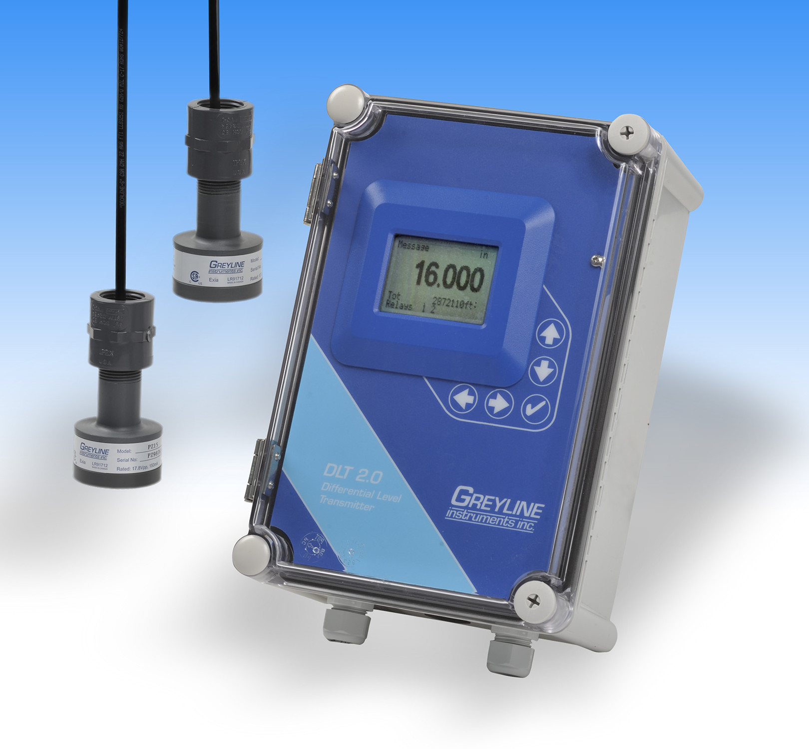
DLT 2.0 Differential Level Transmitter
Reduce costs and simplify instrumentation at treatment plant headworks. The DLT 2.0 can measure both differential level plus flow through a flume. Install one Sensor on each side of a mechanical barscreen to continuously monitor, transmit and control level. Use the built-in control relays or 4-20mA outputs to automatically activate the barscreen rake at preset levels.
The DLT 2.0 is a simple solution for barscreen level control at wastewater treatment plants, pump stations and combined sewer systems. It includes two non-contacting ultrasonic sensors to measure level. With sensors positioned above a channel, up and downstream from the barscreen, the DLT 2.0 can display and transmit differential level. The downstream sensor can also be installed above a flume or weir to measure and totalize open channel flow.
Three 4-20mA outputs are configured to transmit upstream level, downstream level (or flow) and differential level. Built-in relays can be calibrated for level control, differential level control or open channel flow.
Other DLT 2.0 applications include two-tank inventory where you can monitor level in two tanks with one instrument. The DLT 2.0 will alternate display of level in both tanks plus transmit 4-20mA outputs. Use the built-in relays to activate alarms or level controls. This versatile dual-sensor instrument can also be configured as a submergence alarm for Parshall flumes.
Contact Greyline Instruments for specific recommendations in your application.
DIFFERENTIAL LEVEL TRANSMITTER SPECIFICATIONS
SCOPE: This specification covers a non-contacting ultrasonic Differential Level Transmitter as manufactured by Greyline Instruments, Massena New York / Long Sault, Ontario. This instrument shall provide for indicating, transmitting and control of level, barscreen differential level and open channel flow through a flume, weir, or other primary measuring device.
A. GENERAL
- Differential Level Transmitter to consist of two non-contacting ultrasonic sensors, connecting cable, and a remote enclosure with indicating, transmitting and controlling electronics.
- Measurement accuracy shall be ±0.25% of Range or 2 mm (0.08"), whichever is greater, and shall be automatically temperature compensated.
- Sensor cable length shall be as required by installation, not to exceed 500 ft (152 m).
- System shall have no moving parts and shall not contact the material being measured.
B. SENSING ELEMENT
- Ultrasonic sensors shall be constructed of PVC.
- Sensors shall have a minimum deadband or blanking of 8" (203.2 mm) and a maximum range of 15 ft. (4.57 m), and have an operating frequency of 92 kHz with an ultrasonic beam angle of 8 Degrees.
- Sensors shall withstand accidental submersion to 20 psi (1.4 bar).
- Sensor operating temperature shall be from -40°F to 150°F (-40°C to 65°C).
- Sensors shall include integral temperature sensor. Temperature sensors requiring separate mounting and wire runs shall not be accepted.
C. SENSOR CONNECTING CABLE
- Provide RG62AU coaxial cable 25' (7.6m) continuous length, with waterproof, potted bond to the Sensor head.
- Extended sensor cable shall be RG62AU coaxial to a maximum of 500' (152m) for each sensor. Cable shall be spliced with screw terminal connections in manufacturer's recommended steel NEMA4 Junction Box.
- Level and temperature signals shall be conducted on one single coaxial cable. Separate or multiple-conductor cables shall not be accepted.
- Sensor cable shall be installed in grounded metal conduit.
D. TRANSMITTER
- The transmitter shall include a built-in 5-Key calibration system with operator selection of parameters through visual prompts from a Menu calibration system. Systems requiring calibration by Parameter codes or external calibrators shall not be accepted..
- Calibration data shall be permanently stored through power interruptions without requirement of a back-up battery.
- Field calibration shall allow selection and automatic conversion of measurement units, measurement span and control relays.
- The transmitter shall provide for field calibration in user-selected Level, Range and/or Open Channel Flow modes. Operation mode shall be user-selectable for differential level, differential level plus open channel flow, level/volume in two tanks or submerged flow alarm in Parshall flumes.
- Transmitter shall permit field programmable damping to smooth output in turbulent level conditions and to disregard false signals from waves and spurious echoes.
- Transmitter electronics operating temperature shall be from -5° to 140°F (-20° to 60°C).
- Transmitter shall have three isolated 4-20mA outputs each with 1000 ohm maximum load. Outputs shall allow field programmable offsets of 4mA and 20mA for level, differential level and open channel flow.
- Provide 2 control relay dry contacts rated 5 ampere SPDT. Relays shall be programmable for level alarm, differential level control, temperature alarm, pump control, pump alternation, flow totalizer pulse and/or echo loss alarm.
- Provide a white, backlit matrix LCD display indicating level, differential level, flow rate, totalizer and relay states in user-selected engineering units.
- Transmitter shall be housed in a wall-mount, watertight NEMA4X (IP 66) enclosure with hinged, clear cover. Mounting hardware shall be included.
- Transmitter LCD display shall be visible without opening cover.
- Transmitter electronics shall include automatic high voltage bleeds for nearby lightning strikes.
- Electronics shall be modular and field replaceable by means of plug-in circuit boards. The instrument shall detect and load software menus automatically for field-installed options.
- The transmitter shall be powered by 100-240VAC 50/60Hz requiring less than 3 Watts.
E. OPTIONAL FEATURES FOR INSERTION AS REQUIRED
- Have 4 additional (6 total) control relays, rated 5 amp SPDT and programmable for level alarm, differential level control, temperature alarm, pump control, pump alternation, flow totalizer pulse and/or echo loss alarm.
- Sensor, connecting cable and junction boxes shall be rated intrinsically safe to Class I,II,III, Div. I,II, Groups C,D,E,F,G.
- Have a thermostat controlled enclosure heater for Transmitter operation at temperatures below freezing.
- Have two PZ34T non-contacting ultrasonic PVC sensors rated for measurement range up to 32 ft (10 m) with minimum deadband or blanking of 16" (406 mm).
- Have manufacturer's recommended enclosure sunscreen to permit Transmitter mounting in direct sunlight.
- Have manufacturer's recommended Sensor sunscreen to permit temperature-compensated Sensor mounting in direct sunlight.
- Have manufacturer's recommended Panel Mount Flange assembly for enclosure installation.
- Have a built-in 2 million point Data Logger with USB output to flash drive or mass storage device.
- Transmitter power input shall be 9-32VDC with maximum power consumption of 3 watts or less.
F. MANUFACTURER
DLT 2.0 Differential Level Transmitter shall be Model DLT 2.0 as manufactured by Greyline Instruments Inc. and shall be warranted against defects in materials and workmanship for one year.