
- Non-Contacting Clamp-on Ultrasonic Transducers
- Works on Metal and Plastic Pipes
- Large Backlit Flow Rate Display and Totalizer
- Isolated 4-20mA Output
- Built-in 5-Key Calibrator
- 2 Programmable Control Relays
- Optional 2 Million Point Data Logger
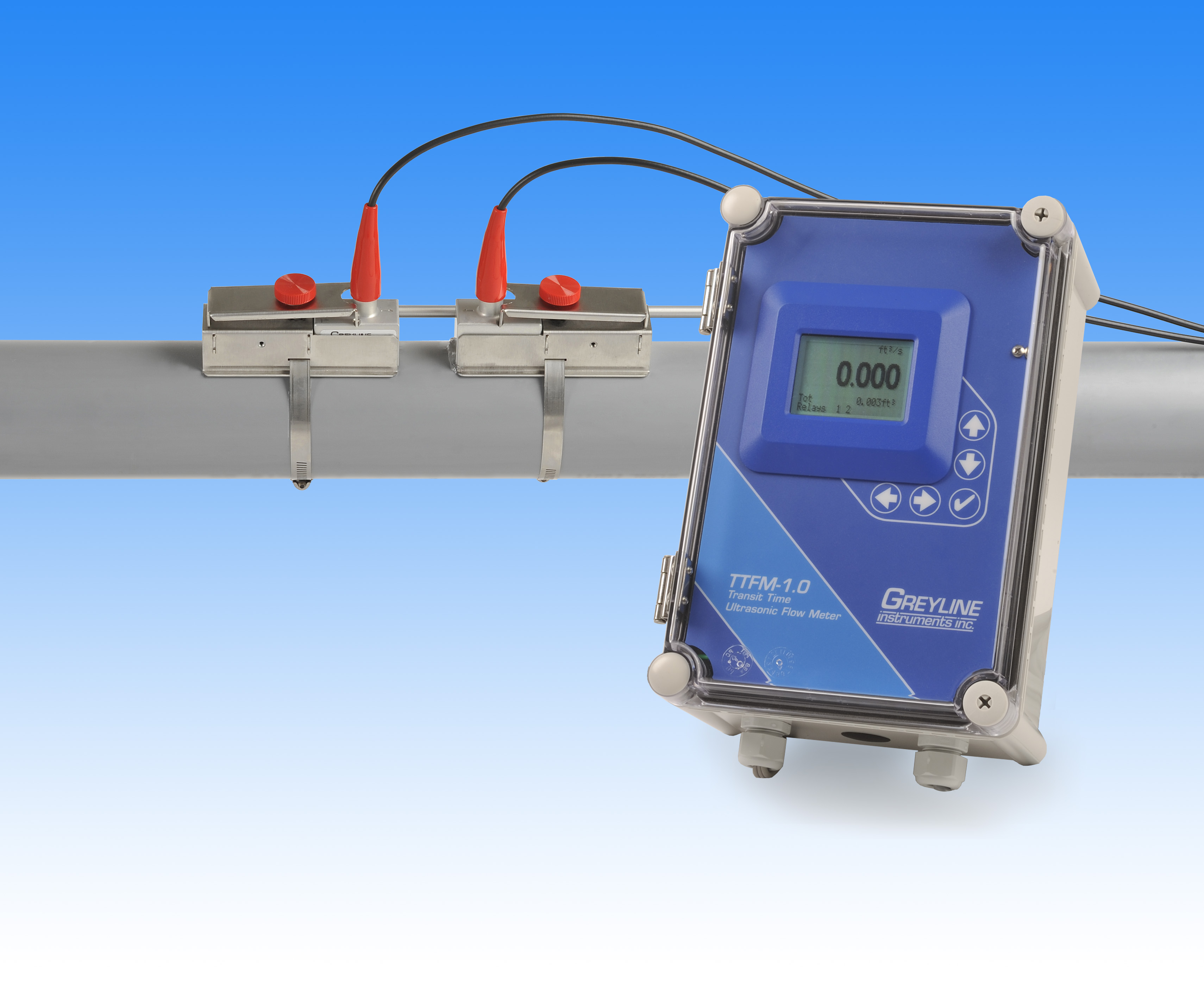
TTFM 1.0 Transit Time Flowmeter
New - TTFM 1.0 Transit Time Flowmeter
Accurately measure the flow rate of clean, non-aerated liquids like water, chemicals, and oils in full pipes. Ultrasonic transducers mount on the outside of a pipe without shutting down flow. Flow rate is displayed on the large, backlit display along with totalizer and signal strength. Use the built-in control relays for flow alarms or flow proportionate pulse. Connect the isolated 4-20mA output to PLC's or controllers.![]()
The TTFM 1.0 works on a wide range of pipe sizes and materials including carbon steel, stainless steel, ductile iron, cast iron, PVC, PVDF, fiberglass, copper, brass, aluminum and pipes with bonded liners including epoxy, rubber and Teflon.
The TTFM 1.0 Transit Time Flowmeter operates by measuring the “transit time” or “time of flight” for ultrasonic sound pulses transmitted from one transducer to another. Depending on the mounting configuration, the signal may cross the pipe once, twice or four times. To measure flow the transit time is compared between ultrasonic signals travelling upstream and downstream.
TTFM 1.0 Standard Features Include:
- pair SE16B ultrasonic transducers - clamp-on for 1/2” to 48” (12 mm to 1200 mm) pipes
- and rated non-incendive for Class I, Division 2, Groups A, B, C & D locations
- sensor cables - pair 25 ft / 7.6 m coaxial with BNC connectors
- flow rate range: ± 0.07 to 39 ft/sec (± 0.02 to 12 m/sec)
- installation - stainless steel transducer mounting brackets and clamps, alignment bar and silicone coupling compound kit
- enclosure - watertight, NEMA4X (IP66) polyester and polycarbonate
- display - white, backlit matrix
- totalizer - 14 digits
- calibration - built-in 5-key programmer
- output - isolated 4-20mA (1000 ohm)
- 2 control relays - 5 amp, SPDT - programmable for flow proportional pulse output, and/or flow alarm
- plug-and-play options including data logger and extra control relays
- power input - 100-240VAC 50/60Hz, 4 Watts maximum
- electrical surge protection and RFI filters - AC, sensor, 4-20mA
Contact Greyline Instruments for specific recommendations in your application.
TRANSIT TIME FLOW METER SPECIFICATIONS
SCOPE: This specification covers an Transit Time Ultrasonic Flow Meter as manufactured by Greyline Instruments, Massena, New York / Long Sault, Ontario. The instrument shall provide for non-intrusive flow measurement, indication, totalizing and transmitting of the flow rate in a full pipe.
A. PERFORMANCE SPECIFICATIONS
- The ultrasonic flow meter shall have an accuracy of ±1% of reading or 0.1 ft/sec (0.03 m/sec), whichever is greater. Have repeatability and linearity of ±0.25%.
- Shall operate on clean liquids in full pipes with less than 2% solids or gas bubbles at flow velocities from ±0.07 to 39 ft/sec (±0.02 to 12 m/sec).
- Operate on the following pipe materials: carbon steel, stainless steel, PVC, PVDF, fiberglass, galvanized steel, mild steel, glass, copper, brass and pipes with bonded liners including epoxy, rubber and Teflon.
B. TRANSDUCERS (FLOW SENSORS)
- The flow meter shall have a dual transmitting/receiving, clamp-on transducers. The transducers shall operate continuously at temperatures from -40°F to 300°F (-40°C to 150°C).
- The standard transducer pair shall be designed to install on pipes with inside diameter ranging from 1/2" to 48" (12 mm to 1200 mm).
- Have 25 ft (7.6 m) length coaxial cables from the electronics with BNC connectors to transducers.
- Shall include manufacturer's recommended sensor coupling compound. Shall include stainless steel mounting hardware with pipe clamps.
- Shall include BNC seal jackets for transducer operation in wet or submerged conditions.
- Transducers shall be rated Non-incendive for Class I, Division 2, Groups A, B, C & D locations.
C. TRANSMITTER
- The transmitter indicator shall be housed in a watertight and dust tight NEMA4X (IP 66) polyester and polycarbonate enclosure with a gasketed shatter proof window, and suitable for wall mounting.
- Flow meter electronics shall be designed to operate at temperatures from -5°F to 140°F (-20°C to 60°C). Electronic circuits are interchangeable with other flow meters having the same model number. The transmitter circuit and calibration frequency standard shall be crystal controlled. The transmitter shall be powered by 100-240VAC 50/60Hz requiring less than 4 Watts.
- The transmitter shall include a built-in 5-Key calibration system with operator selection of parameters through visual prompts from a Menu calibration system. Systems requiring calibration by Parameter codes or external calibrators shall not be accepted.
- The 4-20mA shall be flow proportional and isolated, with programmable zero and full scale offsets. Maximum resistive load shall be 1000 ohms. It shall include automatic high voltage bleeds for nearby lightning strikes.
- Shall include noise suppression circuitry to filter electrical interference.
- Have a white, backlit matrix LCD display indicating flow rate in user-selected engineering units, units of calibration, relay states, signal strength and 14-digit totalizer.
- Have 2 control relays rated 5 ampere SPDT. Relays shall be programmable for flow proportional pulse output, or as flow rate alarms with separate ON/OFF set points.
- Shall display and totalize forward and reverse flow.
- Electronics shall be modular and field replaceable by means of plug-in circuit boards. The instrument shall detect and load software menus automatically for field-installed options.
D. ADDITIONAL FEATURES FOR INSERTION IN SPECIFICATION AS REQUIRED:
- Transducer cables shall be 50 ft (15m) length coaxial with BNC transducer connections.
- Transducer cable shall be extended length shielded coaxial pair up to 250 ft (75 m) with NEMA4X (IP 66) Junction Box.
- Transducers shall be rated Intrinsically Safe for Class I, Division 1, Groups C and D; Class II, Groups E, F and G; Class III; Type 4 hazardous locations.
- Have a thermostatically controlled AC-powered enclosure heater for condensation protection in locations with temperature below -5°F (-20°C).
- Have power input of 9-32VDC.
- Have 4 additional (6 total) control relays, rated 5 amp SPDT and programmable for flow rate alarms or flow totalizer pulse.
- Have a built-in 2 million point Data Logger with USB output to flash drive or mass storage device. Include Windows software.
E. MANUFACTURER